230V Air Conditioner and HomeKit, part 10: Are We Done Yet?

Of course not!

The setup I described in my previous post has an issue that’s not obvious: the fans are on all the time. They’re powered by the +5V pins on the Raspberry Pi.

The fans were pretty quiet, but they were still audible in a quiet room. It was also a waste of power. I wanted the fans to only turn on when power was supplied to the solid-state relays.

At first, I had the brilliant idea of attaching the fans to GPIO pins, just as I had done with the relays. Fortunately, I did some homework; otherwise Goldy would have mocked me for days. It turns out that while the +5V pins can easily supply the 200mA required by the fans, the GPIO pins can only supply 16mA. If I had plugged the fans into the GPIO pins, it might have damaged the RPi’s circuit board.

Fortunately, I found this page which contained a simple circuit for controlling the fans from a GPIO pin. Here’s the circuit diagram from that page, redrawn by me:

Fan circuit

I included some extra details in my diagram, because I hadn’t worked with transistors in years and needed the B, C, and E pins labeled on the diagram. It was also the first time I ever worked with diodes. I read up on working with transistors and diodes so I’d be able to tell how to put them in the circuit. I had some old 470Ω resistors, 2n222 transistors, and a breadboard from my old wizards’s staff project, but since I had to get new diodes and a breadboard jumper wires anyway, I decided to spend the extra few bucks for new breadboards and transistors.

Here’s what it looked like when I installed two sets of components for the above circuit and tested it with my Raspberry Pi:

Fans and breadboard

It’s a bit of a mess, but it worked: I could turn the fans on and off via gpio commands.

Next I put the assembly in the box, which made things look even messier:

Breadboard in box

Again, it all worked.

I’m aware that for a “finished” product, I should have transferred the transistors, diodes, and resistors to a printed circuit board. In fact, they make circuit boards of the same size, shape, and pin layout of the breadboard so you can transfer the components to the same sockets and solder them in place. However, I wasn’t prepared to try to resurrect my old soldering skills. The breadboard came with a sticky backing that I used to fix it in the box. So far, none of the components have shown any inclination to shake themselves loose.

Next came getting the box mounted on my wall near the air conditioner. I quickly learned two things:

  1. The project enclosure box was not designed to be mounted on a wall.
  2. The cable of the micro-USB power supply that came with the Canakit was not long enough to reach from where I wanted to mount the box to the nearest available electrical outlet.

To deal with the first issue, I drilled some holes in the wall and use dry-wall anchors and bolts that fit in indentations in the back of the box. That wasn’t enough to hold it up, so I added some angle brackets:

Box mount

That still wasn’t enough, so finally I conceded “defeat”, drilled a couple of additional holes in the back of the box, and used dry wall screws to fix it in place:

Box on the wall

You can see my expert carpentry skills: Even though I used to a level to set up everything, the box still came out slightly crooked. Fortunately, it’s located behind my TV set where it’s not visible to the casual observer.

To handle the second issue, I purchased a USB charger and a separate 10-foot-long micro-USB charger cable. Before I placed the box on the wall, I tested this combination for several days to make sure the Raspberry Pi wouldn’t overheat or display any unusual symptoms.

As I type these words, my air conditioner has been running for several hours with power supplied through this box. The heat sinks are only slightly warm at best. Goldy is still nervous, but she’s becoming more relaxed with each passing hour.

Alternatives

In the first post in this series, I asked if there was any existing way to control a 230V air conditioner via HomeKit. It wasn’t until half-way through the project that I found this Reddit post. It turns out that people who own pool water heaters have to deal with this problem too, and they have several solutions.

Of the ones discussed in that post, if I had known about it I would have purchased the ELK-9200 Heavy Duty Relay. Its containing box is 12″x12″x3″, somewhat larger than the enclosure I went with, but it’s designed by professionals and is doubtless safer. I still would have had to cut apart power cords, so Goldy would still have cause to be anxious (and you would still have to read part 7).

On the other hand, if you’ve added up the cost of all the materials I purchased for this project, the ELK-9200 would have cost about half as much.

Wrapping it up

Here we are, at the end of my longest series of blog posts since I wrote about a road trip I took in 2008. That saga had radiant fruits of passion; this saga had an imaginary talking goldfish. It all balances out.

I now have the parts for future Maker projects if I’m so inclined. I have a Raspberry Pi, which is a pretty decent little computer. I may install another HomeBridge module that would give me some control over my PS4.

I learned quite a bit, I made a new imaginary friend, and got some more practice writing blog posts. All in all, it was a positive experience.

230V Air Conditioner and HomeKit, part 9: The Box

I knew from the start of this project that I’d need to put all the components in an enclosure. This was to be a semi-permanent installation; I couldn’t have wires and heat sinks dangling everywhere.

Sam Groveman suggested this type of project box. I picked one that would be big enough to hold the solid-state relays along with their heat sinks. Here’s a picture of just the box:

Project box

The size of the box is roughly 12″ x 10″ x 5″, a bit large, but I later became glad I had the extra room to work in it. Those round things on the side of the box are grommets; you can see that I took one out for the picture. The grommets could be easily cut with Xacto knives. I cut small holes in them so that hot air (if any) could circulate through the box, but hopefully discourage insects and cat hair from getting inside.

The lid of the box screws attaches to the base with screws, and there’s a thin rubber gasket around the rim of the lid. Of course, once I cut holes in the grommets the box was no longer water-tight. It’s described as an “electrical project enclosure” but I am under no delusion that this applied to house current. This means I wanted everything in the box to be secure and that no metal part that carried 120V AC would be exposed.

As I mentioned in part 6, I wanted to use fans powered by the Raspberry Pi to cool down the heat sinks. The problem was the fans’ wires weren’t long enough. So I extended the fan wires:

Extended fan

I got a heat-shrink set so I could splice the wires from the fans to the jumper cables.

I followed a suggestion from Sam and used scrap wire to tie the fans to the heat sinks. It looked inelegant, but it worked:

Fan attached to heat sink

The heat sinks came with screws to attach them to the solid-state relays, but no screws to attach them to a project box. So I purchased a set of small nuts, bolts, and washers, along with a cheap tap wrench with taps that corresponded to those screws. I marked where I wanted to put the bolts inside the box, used a Dremel to drill a hole in that spot, and tapped the hole from the outside. I was pleased to see that the bolts screwed into the holes and held nicely until I could get the washers and nuts on them.

The Raspberry Pi case did not not have any mounting holes, and neither does a “bare” RPi board. I settled for attaching the case to the box with adhesive Velcro strips; I guessed (correctly as it turned out) that I would want to take that case out the box frequently for various adjustments.

Here’s the final layout of the box:

Cords held with Sugru

You can see that I held the power cords in place with Sugru. It hardened nicely and I could tug on the cables without them budging. However, it probably would have been less expensive if I used gasket sealant.

Now came the part that Goldy was dreading (and this is your last chance to read part 7 again before you put her life on the line): I plugged the power cord into the NEMA 6-15 outlet. No sparks or flares or anything of the sort. I told HomeKit to turn the circuit on and off… and it didn’t work.

Goldy breathed a sigh of relief. Then she started laughing. It was not her finest moment.

What do I mean by “it didn’t work”? For the first test, I didn’t plug the air conditioner into the female end of the extension cord; if something were to go wrong I didn’t want to damage it. Instead, I used my multimeter to measure the AC voltage at the female end of the cord. When HomeKit turned the relays on, the voltage was 120V AC. When it turned the relays off, the voltage went down to 117V AC, but it did not turn off.

I talked it over with Sam. His first suggestion was that solid-state relays might require a load to function. Then he did some web searching and found this primer on solid-state relays. We looked it over. Perhaps I’d purchased the wrong kind of SSR for the project; I wasn’t sure whether I’d need SSRs that could handle resistive loads instead of inductive loads. Sam thought using a mechanical relay instead of a solid-state relay might be a better choice; then I wouldn’t have to worry about the type of load.

I thought I’d give it one more try before I ordered new relays. This time I would perform the full test, and plug the air conditioner into the hacked extension cord. Goldy covered her eyes with her fins, and…

It worked perfectly. Sam’s first suggestion was the correct one. I later scrolled to the bottom of that primer and confirmed that SSRs require an actual load to function. My multimeter was not sufficient.

I verified I could turn the A/C on and off using HomeKit. Then, as Goldy watched apprehensively, I left the system on for 45 minutes. Again, no sparks, no fumes. Those heat sinks remained at room temperature as far I could tell. Maybe the fans made a difference, but I doubt it.

My knowledge of AC circuits isn’t quite good enough to extrapolate how many watts should be dissipated by an SSR from its data sheet. If I use a calculator like this one and assume a 1.6V voltage drop from the data sheet at a maximum of 15 amps, the power loss within the relay should be about 24 watts. If I believe that number, I might expect the relays to get as warm as a modern florescent bulb. I didn’t even detect that much heat.

The project works! Yay!

So this should be my last blog post on the subject, right? Goldy is giggling. We may learn the reason why in the next installment: “Are we done yet?”

230V Air Conditioner and HomeKit, part 8: Power Cords

Did you read part 7 yet? If you thought to yourself “I don’t need to read part 7” that means you need to read part 7. (The exception is if you’re a licensed electrician, of course.)

Now I’ve reached the stage that Goldy is dreading: Working with power cords.

The point of this project was to use the solid-state relays attached to a Raspberry Pi to control the two “hot” power lines of my air conditioner using Apple’s HomeKit. I knew that this would require cutting open a power cord.

I knew I wasn’t going to cut apart my air conditioner’s power cord. If anything went wrong, I’d wind up with a dead A/C. Instead I purchased a NEMA 6-15 extension cord in order to cut it up. Here’s a picture of the two ends of the cord:

NEMA 6-15 extension cord

As a test, while I worked on the other steps of this project I describe in previous posts, I plugged male end of the extension cord into my apartment’s NEMA 6-15 outlet. With a multimeter, I verified that both “hot” wires (the horizontal sockets) were at 120 volts AC with respect to ground. Then I plugged my air conditioner into the female end of the cord and ran it for several hours. There were no problems, anomalous warm spots, or any other indication that the cord and A/C weren’t functioning as they were designed to do.

I removed the extension cord and did one last check with my multimeter. The resistance from the male to female ends of the extension cord for the corresponding poles to sockets was 0.2Ω. Nice job, Yung Li! Then I cut open Yung Li’s lovely power cord in the middle:

Peel off extension cord cover

Not shown is the cut on my thumb I got when the Xacto knife slipped.

Now I had to figure out which of the three wires (white, black, or green) was the ground wire. If I’d had to guess, I would have guessed black, since that was the standard color of a ground wire in the electronics work I’d done so far. I would have been wrong. (You did read part 7, right?)

Fortunately, I did some homework. After searching on the web for a bit, I found found a couple of sites (like this one) that included pictures of the innards of a 6-15 power cord. Here’s the relevant image from the page I just linked:

6-15p to 6-20R spec shot

Evidently the standard is that the green wire is ground.

With a prayer to both Guan Yin (Goddess of Mercy and Compassion) and Yung Li (Taiwanese manufacturer of the power cord), I cut the black and white wires. My multimeter verified that there was still continuity from the ground pole to the ground socket of the cord.

When I stripped the ends of the wires I’d cut, I saw that the wires were stranded. That was fine and not entirely unexpected. Sam Groveman felt that wrapping stranded wire around the screw terminals of a solid-state relay might be tricky (and dangerous; did you read part 7?), so instead he recommended that I get spade terminals and crimp them to the end of the wires. Here’s what the terminals looked like:

Spade terminals

Here’s the initial set-up:

Extension cord into relays

At this point, I hadn’t plugged the assembly into a power line yet. All I could do is verify my previous results: When HomeKit turned the relays off, the continuity between the two ends of the same line in the power cord was off; when the relays were on, the resistance between the two ends was about 6 kΩ. I knew that resistance from a multimeter had little meaning for alternating current (that’s why AC won over DC for household electricity), but it was reassuring nonetheless.

I’m sure you’re curious about how this worked when I applied AC power to this setup. However, before I tested that, I wanted to get the whole thing into a box; if there were going to be any problems, I didn’t want see them in a pile of relays and heatsinks and an RPi all dangling around.

I’ll get into the next step, and we’ll learn Goldy’s fate, in the next installment: the box.

230V Air Conditioner and HomeKit, part 7: Electrocuting Goldfish

In my previous post in this saga, I’d just reached the point when I start talking about power cords.

Before I go any further, we have to deal with some practical stuff.

Starting with my next post on this project, I’m going to describe how I worked with wires that carry household current. These lines carry 120V AC and go up to 15 amps.

Perhaps you’ve been reading these posts to learn how to start on your own first Maker project. Or maybe you enjoy the tale of how Doctor Doofus, a particle physicist and so-called intelligent man, is fumbling his way through electronics and making a big deal of something that other folks have described in five paragraphs.

What you may not have considered is that following in my footsteps may lead you to burning down your house, or electrocuting both yourself and your pet goldfish.

I’m a physicist, but I’m not a trained or licensed electrician. You may be surprised what a scientist who fixates on sub-atomic particles does not know about practical matters. This project has an element of risk, and though I try to be careful, I’m almost certainly making a false risk assessment.

That does not mean you should consider taking the same risk. You need to be cautious with your own life, as well as the life of your goldfish, Goldy. Any project that involves AC power requires expertise that neither I, you, nor Goldy possesses.

Let’s take a look at a bit of information that I only learned a couple of days ago. I did not know this, but a licensed electrician would: Even if you are working with wire of the correct gauge, you should not screw down braided wire if that wire will carry household current. Braided wire can expand and contract as current is turned on and off. This can lead to gaps in the connection, which leads to arcs, which can easily lead to fires. If you’re going to screw down household wiring, it should be solid copper.

That’s one fact, and as you’ll see in the next part I avoided that issue. But that’s one fact out of hundreds that a licensed electrician knows, either through training or experience.

Also, although I’m being wordy, stretching out my descriptions until they rival the Epic of Gilgamesh, I’m not setting down every detail. I’m not describing every test I did, every piece of electrical tape I applied, every measurement I made with a multimeter. I’m not even linking to every web site I read investigating similar projects. I have some experience with wiring and electronics, but it’s a long way from Heathkits to an electrician’s license.

For Goldy’s sake, I urge you to pay attention:

I am not a licensed electrician. I am describing a project that I did. My descriptions are not meant to be a ‘how-to’. The project I describe involves working with household currents that can cause fires or electrocution. Consult with a licensed electrician before trying to duplicate this project or do any other project that uses household current.

In no way will I be responsible for any damage or harm that comes from you trying to duplicate any step of what I describe in this series of posts.

You should also consider reading a more emphatic warning for a project that also used a Raspberry Pi to control AC power.

Do as I say, not as I did. Goldy would you be proud of you.

In part 8: Power Cords.

230V Air Conditioner and HomeKit, part 6: Solid-State Relays

In the last part of this overly-extended saga, I described how I got a Raspberry Pi to send signals to the pins on its circuit board. The next step is to get the signal from those pins to control the flow of electricity through a 240V power cord.

I found several posts on the web (here’s one) that suggested a good way to do this was with solid-state relays. Here’s the picture from that last link:

SSR picture

The idea is that a low voltage can be turned on or off on the lower terminals of the relay, and that will allow or block a high voltage across the upper pins. From the label (and the technical specs) of that relay, I knew that from 3V-32V volts DC on the two lower terminals could control up to 380 volts AC on the upper terminals; the GPIO pins would be at 3.3V when turned on and a NEMA 6-15 power cord would carry around 120V AC per wire. The label on both the air conditioner and the rating of the power cord told me that the relay would have to handle up 15 amps, so I got a relay that could handle 40A.

In other words, I made sure to get a relay with specs much higher than I would need to handle the volts and amps it would be switching.

Did I trust that? No, of course not! When you pass that much voltage and amps through a small device, the chief risk is that it might get hot. This is a recognized issue with solid-state relays, and they make special heat sinks for them. I purchased this set of three, which came with the necessary screws to attach the relays. I also picked up some thermal paste to improve the heat transfer between the relay and the heat sink.

Here’s one of the heat sinks:

Heat sink

Was that enough? I still wasn’t sure. So I got a couple of fans that could be powered by the 5V pins on the Raspberry Pi. That’s why you can see a fan in most of the Raspberry Pi pictures; I wanted to make sure it would keep spinning no matter what I did.

I connected the relays to the GPIO pins (while the Raspberry Pi was off, of course):

Relays, AC off

Then I turned on the voltage on the Raspberry Pi using Homekit:

Relays, AC on

Aha! The LEDs on the relays turned on! At least up until this point, I was doing something right.

I used a multimeter to see if I could spot anything across the the upper terminals of the relays. I found that with the relays off, a continuity test failed; with the relays on, the resistance across the upper terminals went to about 6 KΩ. This demonstrated that some electrical characteristic was changing in the upper terminals in response to the signal on the lower terminals, though it didn’t prove the relays could switch 120V.

Everything was fine until I turned the Raspberry Pi and then on again. For about 15 seconds after I turned it on, the LEDs on the relays were “half-lit”:

Relays during boot

My multimeter read 1.6V across the GPIO pins during this time. The top terminals of the relays remained off, but I still wasn’t happy. I didn’t want there to be any chance that my air conditioner would turn on just because my apartment had a power outage.

It was Sam Groveman who gave me the answer. I used my chosen GPIO pins on the Raspberry Pi as output pins. On an RPi, an output pin doesn’t need a pull-down resistor; the output pins are automatically pulled. However, when the RPi boots up, by default all the GPIO pins are set to input, with no defined output voltage. An input pin does need a pull-down resistor; otherwise the voltage “floats”. When my multimeter read 1.6V, it was probably because the actual voltage was fluctuating rapidly between 0 and 3.3V.

I tried to solve the problem by explicitly turning off the pins as part of the boot process. I put the “turn-off” command in /etc/rc.local. But the contents of that file are executed at the very end of the boot procedure, so the relays did not go into a genuine “off” state until 15 seconds after the RPi powered on.

I looked up how to change the default pin behavior. That procedure turned out to be tricky because I used NOOBS to install the operating system. In retrospect, I should have done a direct Raspian image installation.

I could have reinstalled Raspian from scratch, but there was a simpler way: put in pull-down resistors. Fortunately, I had some left-over 10 KΩ resistors from a different project I worked on in 1990.

The final circuit diagram, pull-downs and all, was:
circuit diagram
After I added those resistors, the LEDs on the relays remained dark through the entire Raspberry Pi boot process. Here’s the set-up with the resistors in place:

Extension cord into relays

If you’re keen of eye, you’ll notice some power cords in that picture and in the circuit diagram. I’ll get to that in a subsequent blog post. Before that, I have to deal with the next step of this project: electrocuting goldfish.

230V Air Conditioner and HomeKit, part 5: GPIO

In part 3 of project blog, I described setting up a Raspberry Pi. In part 4 I went over how I installed Homebridge on the RPi so that it could communicate with Apple’s Homekit.

Everything I described in those two parts did not require a Raspberry Pi; I could have done it on my desktop Mac. Now we come to the part that makes the RPi useful: The ability to easily access the pins on the printed-circuit board.

RPi closedup

In the above picture, you can make out the pins on the RPi board near the bottom. (In retrospect, I should have removed the case cover for the photo.) The Raspberry Pi gives you a relatively easy way to control those pins.

Here is a description of the RPi 3B+ pins. The diagram from that page is:

RPi pins

I needed some help from Sam Groveman to understand this diagram. Here’s a longer description than the one he gave, since I have trouble being brief:

  • The small number next to the picture of a pin is the physical pin number, the one you get if you just count the pins across and down.
  • The big, bold numbers on the right and left sides of the diagram are the GPIO numbers assigned to the pin in the WiringPi package (more on this below).
  • The text between the numbers refers to the electrical function of the pin.
  • This page gave me the basic idea of what I’d have to do (even though the technique described uses an Arduino instead of directly using the Raspberry Pi). I would need to send signals to two solid-state relays in order to control power to my 230V air conditioner.

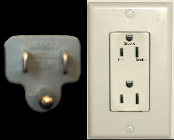
    Why two relays? All of pages I found on Raspberry Pi control of appliances using solid-state relays (SSRs) assumed that the RPi would only have to affect a single power wire. This is because those appliances used a NEMA 5-15 plug:

    NEMA 5-15

    In the above picture, you’ll see that only one hole in that nicely-labeled socket is “hot”, that is, it’s the only one that carries 115 volts. If I want to turn off the power to a device with a NEMA 5-15 plug, it’s sufficient to cut the power to the “hot” wire.

    My air conditioner uses a NEMA 6-15 plug:

    NEMA 6-15

    While the topmost hole is still ground, the bottom two horizontal holes are both at 115 volts. So to turn off my air conditioner, I have to cut power to both “hot” wires.

    (115V + 115V = 230V, which sounds like a consistent bit of math given that I talk about a 230V air conditioner. Actually, if the two wires are out-of-phase and come from three-phase power, the result is 208V. As I said in part 2, I can’t tell which applies to my air conditioner, but it doesn’t matter for the purposes of this discussion.)

    (Could I get away with just cutting the power to one of those two hot wires? According to a friend of mine who works with electrical circuits, it would probably have the same effect as a brown-out. The motor would try to continue running and would burn out. Maybe modern air conditioners would handle it differently, but my A/C is about 40 years old.)

    So I need to control two solid-state relays; I’ll describe the SSRs in more detail in the next blog post for this project. That means I need to control two pins on the Raspberry Pi to turn those relays on and off, plus two more pins that are permanently set to ground in the above diagram.

    Fortunately, the Raspberry Pi operating system, Raspian, comes with the WiringPi package. The key program that’s useful for my project is gpio. Here’s what I see when I use the ‘gpio readall’ command on my Raspberry Pi:

    $ gpio readall
     +-----+-----+---------+------+---+---Pi 3+--+---+------+---------+-----+-----+
     | BCM | wPi |   Name  | Mode | V | Physical | V | Mode | Name    | wPi | BCM |
     +-----+-----+---------+------+---+----++----+---+------+---------+-----+-----+
     |     |     |    3.3v |      |   |  1 || 2  |   |      | 5v      |     |     |
     |   2 |   8 |   SDA.1 |   IN | 1 |  3 || 4  |   |      | 5v      |     |     |
     |   3 |   9 |   SCL.1 |   IN | 1 |  5 || 6  |   |      | 0v      |     |     |
     |   4 |   7 | GPIO. 7 |  OUT | 0 |  7 || 8  | 0 | IN   | TxD     | 15  | 14  |
     |     |     |      0v |      |   |  9 || 10 | 1 | IN   | RxD     | 16  | 15  |
     |  17 |   0 | GPIO. 0 |   IN | 0 | 11 || 12 | 0 | IN   | GPIO. 1 | 1   | 18  |
     |  27 |   2 | GPIO. 2 |   IN | 0 | 13 || 14 |   |      | 0v      |     |     |
     |  22 |   3 | GPIO. 3 |   IN | 0 | 15 || 16 | 0 | IN   | GPIO. 4 | 4   | 23  |
     |     |     |    3.3v |      |   | 17 || 18 | 0 | IN   | GPIO. 5 | 5   | 24  |
     |  10 |  12 |    MOSI |   IN | 0 | 19 || 20 |   |      | 0v      |     |     |
     |   9 |  13 |    MISO |   IN | 0 | 21 || 22 | 0 | IN   | GPIO. 6 | 6   | 25  |
     |  11 |  14 |    SCLK |   IN | 0 | 23 || 24 | 1 | IN   | CE0     | 10  | 8   |
     |     |     |      0v |      |   | 25 || 26 | 1 | IN   | CE1     | 11  | 7   |
     |   0 |  30 |   SDA.0 |   IN | 1 | 27 || 28 | 1 | IN   | SCL.0   | 31  | 1   |
     |   5 |  21 | GPIO.21 |   IN | 1 | 29 || 30 |   |      | 0v      |     |     |
     |   6 |  22 | GPIO.22 |  OUT | 0 | 31 || 32 | 0 | IN   | GPIO.26 | 26  | 12  |
     |  13 |  23 | GPIO.23 |   IN | 0 | 33 || 34 |   |      | 0v      |     |     |
     |  19 |  24 | GPIO.24 |   IN | 0 | 35 || 36 | 0 | IN   | GPIO.27 | 27  | 16  |
     |  26 |  25 | GPIO.25 |   IN | 0 | 37 || 38 | 0 | IN   | GPIO.28 | 28  | 20  |
     |     |     |      0v |      |   | 39 || 40 | 0 | IN   | GPIO.29 | 29  | 21  |
     +-----+-----+---------+------+---+----++----+---+------+---------+-----+-----+
     | BCM | wPi |   Name  | Mode | V | Physical | V | Mode | Name    | wPi | BCM |
     +-----+-----+---------+------+---+---Pi 3+--+---+------+---------+-----+-----+

    This is similar to the diagram above, but with a few more columns.

    • The “BCM” columns refer to the wires coming out of the main processor chip of the Raspberry Pi, and can be ignored for this project.
    • The “Mode” column indicates whether the pin is set to reading signals (IN) or sending signals (OUT).
    • The “V” column, at least for wires that send signals, indicates whether the pin is at 3.3V (V=1) or 0V (V=0).

    I knew I was going to have to connect wires from the Raspberry Pi to the relays. To make things easier on myself, I purchased jumper cables:

    Jumper Cables

    The individual cables peel off cleanly from the wide strip, and the black tips fit nicely over the Raspberry Pi’s pins.

    (Sam Groveman initially suggest that I get a Raspberry Pi Zero W, which is smaller and less expensive than the Raspberry Pi 3 B+ I purchased. However, I would have had to solder wires directly to the smaller RPi’s circuit board.

    (I’ve soldered electrical circuits before, but that was when I worked with Heathkits as a teenager. I figured that fine work that a 14-year-old could handle might be a bit much for someone in his 50s, and went with a bigger RPi and jumper cables. After all, while 14-year-old me had better eyesight, the current me has more disposable income.)

    With lots of pins to choose, I arbitrarily chose pin 29 (GPIO.21) and pin 9 (ground) to form the control circuit for the first relay, and pin 31 (GPIO.22) and pin 39 (ground) to control circuit the second relay.

    I’ve picked my pins, and I’ve set up Homebridge. Now I needed a link between the two. There are several Homebridge plugins for directly controlling Raspberry Pi pins, but all the ones I found would only control one pin at a time. I decided to use the homebridge-cmdswitch2 plugin, which allows you to run your own UNIX commands via HomeKit.

    Installing homebridge-cmdswitch2 was simple:

    npm install -g homebridge-cmdswitch2

    I then had to write the commands that this plugin would execute. I decided to write a single script using the Bash shell, because it’s easier to execute command-line programs like ‘gpio’ directly from the script.

    Here is what I wrote in /home/seligman/multi-pin.sh:

    #!/bin/bash
    # 08-Jul-2018 WGS
    
    # Script to control the operation of multiple pins on the Raspberry Pi
    # at the same time. Here it's used to control multiple relays that
    # affect the power going to my 230V (or maybe 208V) air conditioner.
    
    # Define some commands, to save typing later.  I use the complete
    # paths to invoke commands, so I don't have to worry about the value
    # of $PATH.
    GPIO=/usr/local/bin/gpio
    ECHO=/bin/echo
    
    # A bash array containing the pins I want to control.  With only two
    # pins, I could do this with a couple of "if" statements instead of
    # loops, but I like to (a) show off, and (b) create generalized code.
    PINS=(21 22)
    
    # Note that I chose to identify pins using their WiringPi
    # numbers. If I wanted to use the physical pin numbers instead:
    # GPIO="/usr/local/bin/gpio -1"
    # PINS=(29 31)
    
    function start {
        # Loop over PINS array
        for PIN in "${PINS[@]}"
        do
    	# Set the pin to output and turn it on
    	$GPIO mode ${PIN} output
    	$GPIO write ${PIN} 1
        done
    }
    
    function stop {
        # Loop over PINS array
        for PIN in "${PINS[@]}"
        do
    	# Set the pin to output and turn it off
    	$GPIO mode ${PIN} output
    	$GPIO write ${PIN} 0
        done
    }
    
    function status {
        for PIN in "${PINS[@]}"
        do
    	# If a pin is off, exit with an error code.
    	# Backticks mean "execute the command and return
    	# the command's output". 
    	if [ `$GPIO read ${PIN}` == 0 ]
    	then
    	    exit 1
    	fi
        done    
    }
    
    # $1 is the first argument to this script.
    
    case "$1" in
        start)
    	start
    	;;
        stop)
    	stop
    	;;
        status)
    	status
    	;;
        *)
    	$ECHO $"Usage: $0 {start|stop|status}"
    	exit 1
    esac

    I made the script executable:

    chmod +x /home/seligman/multi-pin.sh

    I tested this script by executing commands like the following, and observing changes to the pins’ state with ‘gpio readall’:

    /home/seligman/multi-pin.sh start
    /home/seligman/multi-pin.sh stop
    /home/seligman/multi-pin.sh status

    Everything worked!

    Then I edited the Homebridge configuration file, /var/lib/homebridge/config.json, to include the homebridge-cmdswitch2 plugin:

    {
        "bridge": {
    	"name": "Homebridge",
    	"username": "B8:27:EB:8F:C5:D7",
    	"port": 45525,
    	"pin": "031-45-154"
        },
        "description": "SmartHome with Homebridge",
        "platforms": [{
    	"platform": "cmdSwitch2",
    	"name": "CMD Switch",
    	"switches": [{
    	    "name": "Air Conditioner",
    	    "on_cmd": "/home/seligman/multi-pin.sh start",
    	    "off_cmd": "/home/seligman/multi-pin.sh stop",
    	    "state_cmd": "//home/seligman/multi-pin.sh status"
    	}]
        }]
    }

    (I had to use the JSON Syntax Checker several times to get all those brackets in the right place.)

    I restarted homebridge so it would use the new configuration file:

    sudo systemctl restart homebridge

    After I did this, I saw that the Eve iOS app on my iPhone recognized “Air Conditioner” as a full-fledged HomeKit accessory, with an ON/OFF switch.

    I spoke into my iPhone: “Turn on the air conditioner.” Siri responded, “Your air conditioner is on.” I attached a voltmeter to the ends of the wires connecting to pins 29 and 9, and saw:

    Air conditioner on

    3.3V (or close enough)!

    Then I spoke to my iPhone again: “Turn off the air conditioner.” Siri responded, “Your air conditioner is off.” And I saw the voltage change:

    Air conditioner off

    I tested this several times, both on pins 29 and 9, and on pins 31 and 39. It all works. HomeKit can control my Raspberry Pi’s pins.

    The next step: Solid-state relays. As a bonus: why there’s a fan connected to the Raspberry Pi in the above two pictures.

230V Air Conditioner and HomeKit, part 4: HomeKit

In my previous post on this project, I described my initial set-up of my Raspberry Pi.

The next step was to interface the RPi (see how nonchalant I’ve become?) to HomeKit, Apple’s mechanism for home automation. There’s already software for this written by the RPi user community: Homebridge.

Homebridge depends on another package, Node.js, which I see as a way of running Javascript outside of a web browser. I followed the instructions on this page (possibly a mistake; I might have been better off with the Homebridge web page) by installing the latest version of Node.js:

wget -O - https://raw.githubusercontent.com/sdesalas/node-pi-zero/master/install-node-v.last.sh | bash

When you do this, you want to want to assure that the system will always be able to find the location of npm:

sudo emacs /etc/profile.d/node.sh

(Remember, emacs is my preferred text editor on UNIX; you may want to use vi or nano. Also note that we’re editing system files, which are normally protected from abuse by ordinary users; you have to use sudo for permission to change them.)

I added the following line:

export PATH=$PATH:/opt/nodejs/bin

After that (and logging off and logging back in again for the above script to work), I could install Homebridge:

npm install -g homebridge

For some reason, there was an installation problem with Homebridge. It was no problem to solve, but I’ll document it just in case someone has the same issue in the future. (I’m going a little out-of-order here, since I didn’t detect this problem until after I started playing with systemd as I describe below).

It turned out that the Homebridge installation was supposed install a separate ‘homebridge’ account, but had not done so. I added the account manually, by editing the system’s password file:

sudo emacs /etc/passwd

I added this line to the end of /etc/passwd:

homebridge:x:911:911:/var/lib/homebridge:/bin/false

That defines a user ID, but users must belong to groups. I edited the system’s group file:

sudo emacs /etc/group

I added the line:

homebridge:x:911:

If you did a web search on the passwd file, you’ll see that I defined the home directory to be ‘/var/lib/homebridge’, since that’s the directory that Homebridge stores its configuration and work files. I had to grant permission for the ‘homebridge’ account to access this directory:

sudo chown -R homebridge:homebridge /var/lib/homebridge

I could start Homebridge just by typing the command

homebridge

Is that good enough? No. I wanted Homebridge to automatically start every time I turned on the Raspberry Pi. To make that happen, I had to fiddle with Raspian’s service manager, systemd. I created a new systemd service file for Homebridge:

sudo emacs /etc/systemd/system/homebridge.service

I put the following in that file:

[Unit]
Description=Node.js HomeKit Server
After=syslog.target network-online.target 

[Service] 
Type=simple 
User=homebridge 
EnvironmentFile=/etc/default/homebridge 
# Adapt this to your specific setup (could be /usr/bin/homebridge) 
ExecStart=/opt/nodejs/bin/homebridge $HOMEBRIDGE_OPTS 
Restart=on-failure 
RestartSec=10 
KillMode=process 

[Install] WantedBy=multi-user.target

I decided I wanted to follow general UNIX standards, and put the Homebridge options in a separate file:

sudo emacs /etc/default/homebridge

I edited it to:

# Defaults / Configuration options for homebridge
# The following settings tells homebridge where to find the config.json file and where to persist the data (i.e. pairing and others)
HOMEBRIDGE_OPTS=-U /var/lib/homebridge

# If you uncomment the following line, homebridge will log more 
# You can display this via systemd's journalctl: journalctl -f -u homebridge 
# DEBUG=*

I had to issue the following command so that systemd would know I fiddled with its configuration:

sudo systemctl daemon-reload

Then I could start running Homebridge using systemd:

sudo systemctl start homebridge

Again, the reason to go through this additional work is that the above command would now automatically be executed every time the RPi was turned on.

There are a couple of ways to monitor the execution of Homebridge. I preferred to look at the system log file using the less command::

sudo less /var/log/syslog

As it stands, Homebridge won’t do much. That’s because it requires two additional components: a configuration file and a plugin to tell Homekit what it can actually do.

I started with a configuration file:

sudo emacs /var/lib/homebridge/config.json

I put in the following lines:

{
    "bridge": {
        "name": "Homebridge",
        "username": "B8:27:EB:8F:C5:D7",
        "port": 45525,
        "pin": "031-45-154"
    }
}

A couple of notes here:

  • The username field I set to the MAC address of the Ethernet port of my RPi. See my previous post for how to find this out.
  • Getting the braces and brackets and commas correct in a JSON file turned out to be tricky. I found a JSON syntax checker that made fiddling with these details much easier.

I restarted Homebridge so it would use the new configuration file.

sudo systemctl restart homebridge

Once I did this, I could run the Eve iOS app on my iPhone. In that app, I went to Setting->Accessories->Add Accessory to Home. I selected manual entry of the new Homekit device, and typed in the same number that I put into the configuration file above: 031-45-154. I fiddled with the accessory’s configuration in the app, and changed its name to “Air Conditioner”.

I originally planned to discuss the next step, controlling GPIO pins on the Raspberry Pi, in this post. Now that I see how long it is, I’ll end things here and discuss GPIO in my next blog post.

230V Air Conditioner and HomeKit, part 3: Raspberry Pi

Warning: For the rest of this series of blog posts about this project, I’m going to take a “golly gee-whiz” approach. If you’re an experienced Maker, computer programmer, electrician, or human being you may be bored by them. However, please feel free to read on and (a) laugh at my ignorance, and/or (b) warn me that I’m about to burn down my home.

In the previous post in this series, I went over why I though it was difficult to replace my air conditioner, and so (with substantial help from Dr. Sam Groveman), I planned to create my own Homekit-based controller to turn my A/C on and off.

The first step in the project was to set up a Raspberry Pi, a small computer designed for use in home projects. I purchased the latest model, a Raspberry Pi 3 model B+, as part of a package from Canakit. This included some nice accessories like a case, an HDMI cable (which I never used; see below), and the Raspberry Pi installation software (NOOBS) on an SD card.

I had no problems following the instructions that came with the kit, and inserted the Raspberry Pi in its case:

RPi assembeled

In the picture, you can see that I installed the optional aluminum heat sinks
on the processor and Ethernet/USB controller; those are the gray vertical ridges you see in the central area of the board. They help keep the chips from overheating during intensive computer tasks. This is not a computationally intensive project, but I decided to play it safe.

Next comes the installation of the Raspberry Pi’s operating system, Raspian. The SD card that came with the Canakit had the software, but I needed a way operate the Raspberry Pi during that installation: a keyboard, mouse, and computer monitor.

There are four USB ports in a Raspberry Pi, and I had plenty of spare USB keyboards and mice that I could take out on loan from work. However, for video display the Raspberry Pi only has an HDMI port, and all the available spare monitors at work were old and only had VGA ports. Foreseeing this, I purchased an HDMI-to-VGA adapter.

When I cabled up the Raspberry Pi to all these devices, it looked like this:

RPi hooked up for initialization

In the lower right is the adapter, with a VGA cable plugged in (the adapter doesn’t come with one). The adapter’s power comes from a USB connector plugged into the Raspberry Pi’s right-hand side, along with the USB keyboard and USB mouse. On the bottom of the Raspberry Pi, the HDMI connector from the adapter is plugged into the HDMI port. The last connector on the lower left is the Raspberry Pi’s power cable, which connects to a power dongle that fits into a standard power outlet.

Again, there were no problems with the software installation. It took a few minutes for NOOBS to install Raspian:

Raspian installation

Edit: It later turned out that it might have been a bit easier if I did a Raspian image install instead of using NOOBS; see part 6.

Following the directions in the Canakit, I logged into the Raspberry Pi and connected it to my WiFi network.

For such a small computer, I was pleasantly surprised at the amount of software that came preinstalled in Raspian. At work I use CentOS and on a Mac there’s Darwin. Raspian is based on Debian, with which I have much less experience. Still, I knew enough to navigate around the directories, look for configurations files, and install my favorite text editor, emacs.

As nice as the Raspian graphical interface was, I wanted to program the Raspberry Pi by connecting to it via ssh from my desktop Macintosh. I enabled the SSH service via one of the preference menus, and noted the IP and MAC address of the Raspberry Pi:

ifconfig.jpg

I got the above by running the Terminal program and typing ifconfig on the command line. (If you’re sharp-eyed, you’ll notice that I created a ‘seligman’ account to use instead of the standard ‘pi’ account. I won’t go into how I did this [since most folks will probably be happy to use ‘pi’] but you’ll see why I did this below.)

The output above told me that my WiFi router had assigned the IP address 10.0.1.10 to the Raspberry Pi; it’s the number after the ‘inet’ in the ‘wlan0’ paragraph. I went to my desktop Mac and verified I could connect to the Raspberry with either ssh pi@10.0.1.10 or ssh seligman@10.0.1.10. That was fine, but of course I wanted more.

I went into my WiFi router’s configuration and told it that the MAC address of the Raspberry Pi (it’s after the word ‘ether’ in the above picture) was always to be assigned the IP address 10.0.10.0. That assured me that the Raspberry Pi would always have the same IP address no matter how or when I rebooted it (unless my router went down, in which case I’d have much bigger problems than fiddling with the Raspberry Pi). Then I edited the contents of a configuration file on my desktop Mac:

sudo emacs /etc/hosts

…adding the line

10.0.1.10 rpi

This meant that from now on, my desktop Mac would interpret the IP name ‘rpi’ as the IP address ‘10.0.10.0’. Now I could login to the Raspberry Pi with ssh seligman@rpi.

Good enough? Of course not! Fortunately, with ssh, if you don’t supply an account name, it assumes the same name as the account you’re using to issue the ssh command. On my Mac, that account is ‘seligman’. So I can login to my Raspberry Pi with:

ssh rpi

Is that good enough? Almost. I still have to type the password for the ‘seligman’ account on the Raspberry Pi every single time I login. Since my network is private, why go through that hassle? I set up passwordless ssh from my Mac’s ‘seligman’ account to the Raspberry Pi’s ‘seligman’ account. Now all I have to do on my Mac is type ssh rpi and I’m on the Raspberry Pi, ready to work.

Since I configured remote access to the Raspberry Pi, there’s no need for the keyboard, mouse, and monitor to be attached to it anymore. Here’s the Raspberry Pi, all configured, accessible, and ready for the next phase of the project:

About the size of a deck of playing cards

I included the deck of cards so you can get an idea of the size of this small computer.

Next up: Homekit and GPIO

230V Air Conditioner and HomeKit, part 2: The Air Conditioning

In what turned to be Part One of an adventure in the Internet of Things, I talked about wanting to control my air conditioner via Apple’s Homekit.

One option I contemplated was replacing my existing air conditioner. To get some idea of what it would take, I removed the front cover, which I’ve done every mumblety-mumble years to clean the filter. Here’s what I saw:

AirConditioner 2018

It’s old and rusty, just as I remembered. It looks like replacing it might be a good idea. I had investigated the procedure for replacing a through-the-wall air conditioner; the instructions begin “Lift the old air conditioner out of the sleeve.” No way. The air conditioner is rusted into place.

To replace the air conditioner would require hiring a contractor. My guess is that it would cost $2000 minimum. I don’t begrudge contractors their money; I charge $120/hour for computer consulting, and that fee is on the very low end. But it’s more than I can afford to replace an appliance that works well, and whose only flaw is being old and unattractive. If we replaced everything that was old and unattractive, I’d find myself in a landfill sooner or later.

Another web site I checked said that old air conditioners were more robust than modern models. The site suggested that you could take an old unit through a car wash to restore it. I’d consider that if I could get the unit out of the wall. But if I could do that, I’d replace the unit anyway.

You can see in the picture that the A/C is missing the knob that controls whether the air exchanger is open or closed. I wrote in my previous blog post that the switch was frozen shut. I tried turning it with a pair of pliers, and it rotated easily. All I need is a new knob. I ordered a cheap knob; if it doesn’t fit, it’s no big deal.

I saw something I hadn’t noticed before: the sticker with the model information for the A/C:

AC Model

Now I knew that I had a Fedders model 4320W. I did a web search, and found nothing. You can give it a try, but I have a hunch that the only significant positive search result you’ll find is this blog post.

That fit in with what I suspected: This A/C has been in the apartment since the complex was built in the 1970s.

The label also gave me some pertinent information for using Homekit switches: Its maximum draw is less than 11 amps and 2100 watts. It also provides about 12000 BTU; no wonder it does such a good job cooling a 400-square-foot living room! I can’t tell whether it’s using 230V or 208V, because apparently it can handle both:

AC Voltage Instructiongs

I don’t want to fiddle with that switch. The only way to know for sure is to use a voltmeter on the outlet providing the power, and that’s difficult for me to reach.

11 amps is well within the capabilities of typical Homekit-style switches and relays. I had a discussion with Dr. Sam Groveman, and emerged with a plan and a Bill of Materials to order. Those parts should arrive during the coming week. I’ll describe the project and assembly in future blog posts.

If you’d to get some idea of what I’m doing without being exposed to my verbosity or waiting for those posts, here’s a description of a similar project. The main difference between that and what I plan to do is that Sam recommended I don’t bother with an Arduino for my setup.

230V Air Conditioner and HomeKit

I could use some advice from anyone with electrical, appliance, and/or construction experience.

I’ve got an old air conditioner in my apartment. It’s the same one I had when I moved in, so it’s at least 30 years old. I’ve also got Apple Homekit set up for other devices in my apartment (light bults and fans).

The goal: control my air conditioner through Homekit. The dream: Before I go home, I turn on the A/C remotely so the apartment will be cool when I get there. Double dream: use Homekit to connect my thermostat to the A/C so that it would turn on if the apartment temperature got over 85 degrees, to keep my pets comfortable.

There are plenty of Homekit devices that plug into conventional wall outlets. Here’s one that I already use.

For those of you keeping score at home, most home plugs and outlets are NEMA 5-15:

This old A/C uses a NEMA 6-15 plug, I think; it’s pretty grungy after 30 years. It looks like this:

AC plug

A new plug of this type looks like this:

The outlet looks like this (it was the best I could do sticking my iPhone behind a bookcase):

AC outlet

This looks like a NEMA 6-20 outlet, but it doesn’t match what’s in use today. A current NEMA 6-20 outlet looks like this:

Again, for those like me who are keeping score at home, this means that my A/C can draw up to 15 amps of current at 240 volts.

The studliest Homekit switch I know of is the Eve Energy Smartplug. It can handle up to 250V, it’s rated for 11A at the most. With my current A/C, even if I could solve the outlet compatibility issues, either a circuit breaker would trip or a fuse would blow if I used it for my air conditioner.

So now we get to the advice I need from people who know what they’re doing:

  • Is it possible to set up some kind of relay so a 15A/120V device can control a 20A/240V device? My web searches suggest that it’s possible, but you need to have electrical experience to construct one and no one has put up any “how to” plans yet. Can you think of something?
  • As I said, my current A/C is over 30 years old. It is certainly not energy efficient. It’s not remote controlled (so devices like Tado won’t work). The latch that lets in air from the outside froze shut 20 years ago, so I can’t use just the fan to vent in cool air when it’s hotter inside than outside. And you can see the picture of the plug above; I’m not sure it’s safe anymore.

    So I’m willing to consider buying a new one. There are Homekit-compatible air conditioners coming onto the market. That leads to contractor-style questions:

    • They make plenty of wall-mounted air conditioners with NEMA 6-15P plugs. I can’t seem to find one that’s Homekit compatible. Do you know of any? (Translation: Is your web-fu better than mine?) Or will I have to accept a Tado-like solution?
    • Alternatively, modern air conditioners draw less current than my old A/C. My living room is about 400 square feet. A decent wall-mounted air conditioner like this one draws less than 5 amps. So it’s theoretically possible to use the Eve Smartplug, if I can solve the outlet compatibility issue.
    • Is it worth solving this problem a different way, by replacing that old NEMA 6-20 outlet with a NEMA 5-15, with a suitable downgrade in voltage? Then an unmodified Eve Smartplug would work. I’m certain that a modern A/C with a NEMA 5-15 plug could handle 400 square feet.
    • How difficult is it to replace a wall-mounted air conditioner? My preliminary web search says that it’s not that difficult, but I’m clumsy when it comes to this sort of work. Is this the sort of thing that I’d have to hire a contractor to do?

      Before you ask: I’ve got a good relationship with my superintendent. He doesn’t mind me doing this sort of work in my apartment, as long as I don’t get him and the landlord involved.

I’ll gratefully listen to any advice, even if that advice must be “Suck it up, Homekit-boy, and live with what you’ve got.”